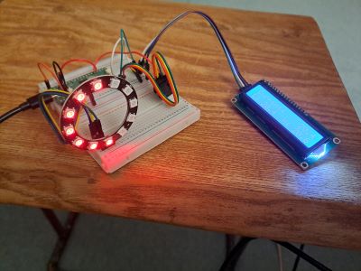
One year later and someone moved the project, sadly some of the wires fell out. So here is how to fix it when this happens again.
Rewire the LCD
The display has 4 outlets.
- Gnd goes to ground, this is anywhere on the blue rail.
- Vcc goes to power, this is anywhere on the red rail.
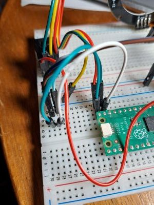
- SDA goes to physical pin 19. This is 19b on my board, and connects to 28c.
- SCL goes to physical pin 20. This is 20b on my board, and connects to 29c.

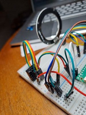
The white on the image is physical pin 19 which we are going to connect indirectly to the Lcd pin marked SDA.
The blue on the image is physical pin 20 which we are going to connect indirectly to the Lcd pin marked SCL.

It is very difficult to see the colours, I could not get a better picture. But basically it is white to white and blue to blue. The wires connected to VCC and GND go to the red and blue rails.
