I saw a post last year from Tyler Glaiel on Medium, and decided to copy his idea and make a mask.
I made the first one, which was really difficult to solder. I moved on to the second. This was a little tidier, but unfortunately it had issues. I had placed the microphone over the nose. The result was that it only worked when you weren’t wearing it.
It is a really difficult soldering project, and I lost the confidence to try again. Hence the led tower soldering practice. Now I have no excuse. Going to have another go.
This is Tyler’s mask in action.
So start with an Arduino Nano. This needs to be loaded up with the code. It was originally shared by Tyler, but he has since withdrawn it, so I’m sorry I am not at liberty to share it.


However this is a rough sketch of where I want everything to go.
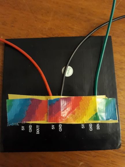
And I want the microphone to sit over these wires, so I need to put down some masking tape – a bit thick to ensure nothing nicks and gets exposed.
I need a 330 Ω resistor between DIN and D6 on the Arduino. I want the Arduino to lie on the opposite end of the led matrix from the DIN connector, so I will try to judge the length right this time.
A7 on the Arduino needs to go to ‘OUT’ on the microphone. This is my last microphone – gently with the solder. There are two secrets to a good joint.
- Be patient. Let the iron warm up properly.
- Don’t try and solder with a blobby tip. I use kitchen roll – doubled over thick so I don’t burn myself. It gently cleans the tip without de-tinning it.
The joint on the microphone is OK. Not so pleased with D6 – blobby tip – I don’t follow my own advice.
Now I just need to solder the black and reds. A lot easier when I plan it up properly.
Note to self. You want the incoming to go to Arduino Vin.
Use the 5V out from the Arduino to power the microphone.
Wire the led direct to the battery. In this way, hopefully the microphone will get a stable power supply and will work reliably. (I might have already blown it).


